iBet uBet web content aggregator. Adding the entire web to your favor.


Link to original content: https://pubmed.ncbi.nlm.nih.gov/38056497
Logical quantum processor based on reconfigurable atom arrays - PubMed Skip to main page content
U.S. flag

An official website of the United States government

Dot gov

The .gov means it’s official.
Federal government websites often end in .gov or .mil. Before sharing sensitive information, make sure you’re on a federal government site.

Https

The site is secure.
The https:// ensures that you are connecting to the official website and that any information you provide is encrypted and transmitted securely.

Access keys NCBI Homepage MyNCBI Homepage Main Content Main Navigation
. 2024 Feb;626(7997):58-65.
doi: 10.1038/s41586-023-06927-3. Epub 2023 Dec 6.

Logical quantum processor based on reconfigurable atom arrays

Affiliations

Logical quantum processor based on reconfigurable atom arrays

Dolev Bluvstein et al. Nature. 2024 Feb.

Abstract

Suppressing errors is the central challenge for useful quantum computing1, requiring quantum error correction (QEC)2-6 for large-scale processing. However, the overhead in the realization of error-corrected 'logical' qubits, in which information is encoded across many physical qubits for redundancy2-4, poses substantial challenges to large-scale logical quantum computing. Here we report the realization of a programmable quantum processor based on encoded logical qubits operating with up to 280 physical qubits. Using logical-level control and a zoned architecture in reconfigurable neutral-atom arrays7, our system combines high two-qubit gate fidelities8, arbitrary connectivity7,9, as well as fully programmable single-qubit rotations and mid-circuit readout10-15. Operating this logical processor with various types of encoding, we demonstrate improvement of a two-qubit logic gate by scaling surface-code6 distance from d = 3 to d = 7, preparation of colour-code qubits with break-even fidelities5, fault-tolerant creation of logical Greenberger-Horne-Zeilinger (GHZ) states and feedforward entanglement teleportation, as well as operation of 40 colour-code qubits. Finally, using 3D [[8,3,2]] code blocks16,17, we realize computationally complex sampling circuits18 with up to 48 logical qubits entangled with hypercube connectivity19 with 228 logical two-qubit gates and 48 logical CCZ gates20. We find that this logical encoding substantially improves algorithmic performance with error detection, outperforming physical-qubit fidelities at both cross-entropy benchmarking and quantum simulations of fast scrambling21,22. These results herald the advent of early error-corrected quantum computation and chart a path towards large-scale logical processors.


Conflict of interest statement

M.G., V.V. and M.D.L. are co-founders and shareholders and H.Z., P.S.R. and T.K. are employees of QuEra Computing.

Figures

Fig. 1
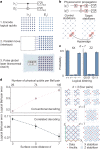
Fig. 1. A programmable logical processor based on reconfigurable atom arrays.
a, Schematic of the logical processor, split into three zones: storage, entangling and readout (see Extended Data Fig. 1 for detailed layout). Logical single-qubit and two-qubit operations are realized transversally with efficient, parallel operations. Transversal CNOTs are realized by interlacing two logical qubit grids and performing a single global entangling pulse that excites atoms to Rydberg states. Physical qubits are encoded in hyperfine ground states of 87Rb atoms trapped in optical tweezers. b, Fully programmable single-qubit rotations are implemented using Raman excitation through a 2D AOD; parallel grid illumination delivers the same instruction to multiple atomic qubits. c, Mid-circuit readout and feedforward. The imaging histogram shows high-fidelity state discrimination (500 μs imaging time, readout fidelity approximately 99.8%; Methods) and the Ramsey fringe shows that qubit coherence is unaffected by measuring other qubits in the readout zone (error probability p ≈ 10−3; Methods). The FPGA performs real-time image processing, state decoding and feedforward (Fig. 4).
Fig. 2
Fig. 2. Transversal entangling gates between two surface codes.
a, Illustration of transversal CNOT between two d = 7 surface codes based on parallel atom transport. b, The concept of correlated decoding. Physical errors propagate between physical qubit pairs during transversal CNOT gates, creating correlations that can be used for improved decoding. We account for these correlations, arising from deterministic error propagation (as opposed to correlated error events), by adding edges and hyperedges that connect the decoding graphs of the two logical qubits. c, Populations of entangled d = 7 surface codes measured in the XX and ZZ basis. d, Measured Bell-pair error as a function of code distance, for both conventional (top) and correlated (bottom) decoding. We estimate Bell error with the average of the ZZ populations and the XX parities (Methods). To reduce code distance, we simply remove selected atoms from the grid, as shown on the right, ensuring unchanged experimental conditions (for d = 3, four logical Bell pairs are generated in parallel). Error bars represent the standard error of the mean. See Extended Data Figs. 4 and 5 for further surface-code data.
Fig. 3
Fig. 3. Fault-tolerant logical algorithms.
a, Circuit for preparation of logical GHZ state. Ten colour codes are encoded non-fault-tolerantly and then parallel transversal CNOTs between computation and ancilla logical qubits perform fault-tolerant initialization. The ancilla logical qubits are moved to storage and a four-logical-qubit GHZ state is created between the computation qubits. Logical Clifford operations are applied before readout to examine the GHZ state. b, SPAM infidelity of the logical qubits without (nFT) and with (FT) the transversal-CNOT-based flagged preparation, compared with physical qubit SPAM. c, Logical GHZ fidelity without postselecting on flags (nFT), postselecting on flags (FT) and postselecting on flags and stabilizers of the computation logical qubits, corresponding to error detection (EDFT). d, GHZ fidelity as a function of sliding-scale error-detection threshold (converted into the probability of accepted repetitions) and of the number of successful flags in the circuit. e, Density matrix of the four-logical-qubit GHZ state (with at most three flag errors) measured by means of full-state tomography involving all 256 logical Pauli strings.
Fig. 4
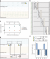
Fig. 4. Zoned logical processor: scaling and mid-circuit feedforward.
a, Atoms in storage and entangling zones and approach for creating and entangling 40 colour codes with 280 physical qubits. b,c, 40 colour codes are prepared with a nFT circuit and then 20 transversal CNOTs are used to fault-tolerantly prepare 20 of the 40 codes, whose fidelity is plotted. Logical decoherence is smaller than the physical idling decoherence experienced during the encoding steps. d, Mid-circuit measurement and feedforward for logical entanglement teleportation. The middle of three logical qubits is measured in the X basis and, by applying a mid-circuit conditional, locally pulsed logical S rotation on the other two logical qubits, the state |0L0L⟩ + |1L1L⟩ is prepared. e, Measured logical qubit parity with and without feedforward, showing that feedforward recovers the intended state with Bell fidelity of 77(2)% (ZZ parities of 83(4)% not plotted; Methods). No mid-circuit refers to turning off the mid-circuit readout and postselecting on the middle logical being in state |+L⟩ in the final readout. By postselecting on perfect stabilizers of only the two computation logicals (error detection in the final measurement), the feedforward Bell fidelity is 92(2)% (not plotted). In d, three of the extra blocks are flag qubits and the other four are prepared but unused for this circuit.
Fig. 5
Fig. 5. Complex logical circuits using 3D codes.
a, [[8,3,2]] block codes can transversally realize {CCZ, CZ, Z, CNOT} gates within each block and transversal CNOTs between blocks. By preparing logical qubits in |+L⟩, performing layers of {CCZ, CZ, Z} alternated with inter-block CNOTs and measuring in the X basis, we realize classically hard sampling circuits with logical qubits. b, Measured sampling outcomes for a circuit with 12 logical qubits, eight logical CZs, 12 logical CNOTs and eight logical CCZs. By increasing error detection, the measured distribution converges towards the ideal distribution. c, Circuit involving 48 logical qubits with 228 logical CZ/CNOT gates and 48 logical CCZs. d, Classical simulation runtime for calculating an individual bitstring probability; bottom plot is estimated on the basis of matrix multiplication complexity. e, Measured normalized XEB as a function of sliding-scale error detection for 3, 6, 12, 24 and 48 logical qubits. For all sizes, we observe a finite XEB score that improves with increased error detection. Diagram shows 48-logical connectivity, with logical triplets entangled on a 4D hypercube. f, Scaling of raw (red) and fully error-detected (black) XEB from e. Physical upper-bound fidelity (blue) is calculated using best measured physical gate fidelities (see Methods and Extended Data Fig. 7 for scaling discussion). Diagrams show physical connectivity. [[8,3,2]] cubes are entangled on 4D hypercubes, realizing physical connectivity of 7D hypercubes.
Fig. 6
Fig. 6. Logical two-copy measurement.
a, Identical scrambling circuits are performed on two copies of 12 logical qubits and then measured in the Bell basis to extract information about the state. Z-basis measurements are corrected with an [[8,3,2]] decoder (when full error detection is not applied). b, Measured entanglement entropy as a function of subsystem size, showing expected Page-curve behaviour for the highly scrambled state, improving with increased error detection. c, Measured and simulated magic (associated with non-Clifford operations) as a function of the number of CCZ gates applied, performed on two copies of scrambled six-logical-qubit systems. d, Pauli string measurement and zero-noise extrapolation using logical qubits. Plot shows the absolute values of all 412 Pauli string expectation values, which only have five discrete values for our digital circuit; Pauli strings with the same theory value are grouped. By analysing with sliding-scale error detection, we improve towards the theoretical expectation values (squares) while also improving towards a purity of 1. By extrapolating to perfect purity, we extrapolate the expectation values and better approximate the ideal values (shaded regions are statistical fit uncertainty).
Extended Data Fig. 1
Extended Data Fig. 1. Neutral-atom quantum computer architecture.
a, Experimental layout, featuring optical tools including static SLM and 2D moving AOD traps, global and local Raman single-qubit laser beams, 420-nm and 1,013-nm Rydberg beams and imaging system for both global and local imaging. b, Level structure for 87Rb atoms, with the relevant atomic transitions used in this work. c, Control infrastructure used for programming quantum circuits, featuring several AWGs. In particular, the moving and Raman 2D AODs are each controlled by two waveforms (one for the x axis and one for the y axis). An additional AWG is used in first-in-first-out (FIFO) mode for rearrangement before the circuit begins and then the moving AOD control is switched to the ‘Moving AWG’. See ref.  for further SLM and pre-circuit rearrangement details, ref.  for further Rydberg AWG details and Rydberg excitation details, refs. , for further Raman laser and microwave control infrastructure details and ref.  for further moving AWG details. All AWGs (other than the ‘Rearrangement AWG’) are synchronized to <10 ns jitter. During Rydberg gates, the traps are briefly pulsed off by a TTL. The FPGA processes images from the camera in real time and, in this work, sends control signals to the Raman 2D AOD for local single-qubit control. d, Example array layout featuring entangling, storage and readout zones. Zones can be directly reprogrammed and repositioned for different applications, as well as specific tweezer site locations. Tweezer beams and local Raman control are projected from out of plane. The entire objective field of view is 400 μm in diameter and, consequently, we do not expect or observe substantial tweezer deformation near the edges of our processor. During two-qubit Rydberg gates, we place atoms ≲2 μm apart within a gate site and gate sites are separated such that atoms in different gate sites are no closer than 10 μm during the gate. At our present n = 53 and two-photon Rabi frequency of 4.6 MHz, the blockade radius is roughly 4.3 μm, such that adjacent atoms are well within blockade and distant atoms are well outside blockade.
Extended Data Fig. 2
Extended Data Fig. 2. Single-qubit Raman addressing.
a, 5S1/2 hyperfine level diagram illustrating the two possible implementations of local single-qubit gates: resonant X(θ) (purple) and off-resonant Z(θ) (turquoise) rotations with two-photon Rabi frequencies ΩRaman. In this work, we use the Z rotation scheme and are blue-detuned by 2 MHz from the two-photon resonance. Owing to Clebsch–Gordan coefficients, Ω~RamanZ=3ΩRamanZ. b, Schematic showing the conversion of local Z(π/2) into local X(±π/2) gates, in which the pulses before (after) the central Y(π) have positive (negative) sign, while leaving non-addressed qubit states unchanged. The Gaussian-smoothed local pulses have duration 2.5 μs for π/4 pulses and 5 μs for π/2 pulses and are performed on single rows at a time with a 3-μs gap between subsequent gates to allow the RF tones in the AODs to be changed (including this, duration is 5–8 μs per row). In this way, arbitrary patterns of qubits, such as the example drawn, can be addressed. c, Calibration procedure used to homogenize the Rabi frequency over a 220 μm × 35 μm array. The position calibration is illustrated for 80 sites: approximate X(π/2) gates are locally performed and the horizontal/vertical position of all tones is scanned in parallel such that a Gaussian fit returns the optimal alignment. After this, powers are iteratively calibrated until the fitted scale factors for the individual RF tones converge to unity. d, Single-qubit randomized benchmarking of local Z(π/2) gates. The local gates are interleaved with random global single-qubit Clifford gates and the final operation Cf is chosen to return to the initial state. Each data point is the average of 100 random sets of Clifford gates and fitting an exponential decay to the return probability quantifies the fidelity F per local gate. Note that we apply all 51 global Clifford gates for each data point, such that errors from the global Clifford gates (as well as SPAM errors) do not contribute to the fitted value.
Extended Data Fig. 3
Extended Data Fig. 3. Mid-circuit readout and feedforward.
a, Single-shot 500-μs local image in the readout zone, in which the peak corresponds to roughly 50 photons collected by the CMOS camera. b, Atomic transition and pulse sequence used for local imaging of ancilla qubits. The data-qubit trap-light shift suppresses data qubit errors, as well as the large spatial separation between entangling and readout zones. We avoid quickly losing the readout-zone atoms during local imaging by using a 5× higher trap depth and we pulse the ancilla qubit traps and local imaging light to image directly on resonance while avoiding negative effects of large trap-light shifts. c, Diagram of components involved in mid-circuit readout and feedforward steps. Atom detection and logical-state decoding occur using the FPGA, which then outputs a conditional TTL to gate local Raman pulses performed on logical qubits in the entangling zone. d, Diagram of approximate timings for a mid-circuit feedforward cycle. First, the F = 2 population is pushed out (in 10 μs) and then the remaining F = 1 population is imaged locally for 500 μs. The 24 rows of pixels covering the readout zone are read out to the FPGA in 200 μs, after which processing is performed. Finally, a conditional TTL output based on the decoded state gates on or off local Raman pulses. The whole readout and feedforward cycle takes less than 1 ms and can be sped up in the future by optimizing local imaging and camera readout. eg, Characterization of the error probability of data qubits during local imaging. e, Data-qubit error probability (fraction of population depumped from F = 2 to F = 1) as a function of local imaging duration out to 20 ms to quantify the effect of the local imaging beam on data-qubit coherence for very long illumination. f, Data-qubit error probability after 20 ms of local imaging, as a function of detuning of the local imaging beam, showing suppression of error red-detuned or blue-detuned from the data-qubit transition. g, Equivalently, increasing the trap depth of the data qubits enables suppression of decoherence owing to the local imaging beam. Because qubits in the readout zone are imaged while their traps are pulsed off, any light shift of the data-qubit transition from the traps contributes directly to the relative detuning. h, For a long, 10.5-ms local beam illumination with optimal local imaging parameters, we observe a 0.7(1)% increase in data-qubit error during an XY8 dynamical decoupling sequence. This suggests a roughly 0.034(5)% error probability for the data qubits during the 500-μs mid-circuit readout image used in this work.
Extended Data Fig. 4
Extended Data Fig. 4. Further surface-code data.
a, Depiction of Bell-state circuit and d = 7 surface codes. b, Diagram showing the transversal CNOT and physical error propagation rules. c, Covariance of the 48 measured stabilizers in both bases. The correlations near the diagonal corresponds to adjacent stabilizers within each block. Strong correlations are also observed with the stabilizers of the other block owing to the error propagation in the transversal CNOT. d, Bell-pair infidelity upper bound (as opposed to estimated Bell-pair error in Fig. 2d; see Methods), showing improvement with increasing code distance. e, Probability of no detected error for each of the 96 measured stabilizers, showing agreement when compared with the theoretical values from empirically chosen error rates (experiment average = 77%, theory average = 82%). Note that X-basis logical 1 and Z-basis logical 2 have higher stabilizer error probability owing to the error propagation in the transversal CNOT (reducing expectation values relative to if the transversal CNOT is not performed). f, Using the empirical error rates that correspond to data-theory agreement for the measured stabilizers in e, our simulations for improvement in Bell-pair error, as a function of code distance, are in good agreement with experiments. The empirical error rates used are consistent with the 99.3% two-qubit gate fidelity, measured for this larger array, as well as the roughly 4% data-qubit decoherence error (integrated over the entire circuit and measured by the Ramsey method). These dephasing error rates are dominated by a complex moving sequence as we prepare the two surface codes in a serial fashion (see Supplementary Video) and would be much smaller for a repetitive error-correction experiment.
Extended Data Fig. 5
Extended Data Fig. 5. Surface-code preparation and decoding data.
a, Surface-code stabilizers for the two independent d = 7 codes following state preparation. The entire movement circuit corresponding to the transversal CNOT is implemented and the transversal entangling-gate pulse is simply turned off. The mean stabilizer probability of success across the 96 total stabilizers is 83%. The high probability of stabilizer success of the two independent codes in both the X and Z bases shows that topological surface codes were prepared (and Extended Data Fig. 4 shows that they were preserved during the transversal CNOT). We note that physical fidelities were slightly lower during this measurement because of calibration drift and, therefore, these results slightly underestimate performance relative to the data in Fig. 2 and Extended Data Fig. 4. b, Logical Bell-pair error while optimizing the decoder by (inversely) scaling the weights of the inter-logical edges and hyperedges that connect the stabilizers of the two logical qubits (higher values correspond to lower pairing weights). More concretely, the probability p of the error mechanism corresponding to the inter-logical edges/hyperedges is scaled and the weights are calculated as log((1 − p)/p). Qualitatively, optimizing this scaling value optimizes with respect to the probability that errors are before or after the transversal CNOT, as errors before the CNOT will lead to correlations between the two logical qubits, corresponding to the inter-logical edges. As the decoder is optimized by tuning the inter-logical scaling factor, the performance for all three code distances improves, and the larger code distances improve faster when approaching the optimal decoding configuration, as expected. These data are consistent with the decoder being properly optimized for all three code distances, consistent with the fact that our improvement with code size does not originate from suboptimal decoder performance for low distance. Note that the y axis is log scale. c, Logical Bell-pair error when using (black) and not using (grey) the ancilla stabilizer measurement values, as a function of the scaling of the inter-logical edges and hyperedges that connect the stabilizers of the two logical qubits. The ancilla measurements contribute to the correction procedure and contribute more for smaller values of the inter-logical scaling, as they correspond to errors that happen before the transversal CNOT. 0× inter-logical scaling corresponds to conventional decoding within the two independent surface codes. For the 1× inter-logical scaling plotted here, the d = 7 inter-logical scaling parameter is chosen slightly different from in Fig. 2d to have consistency across the three code distances (which produces measured values within error bars).
Extended Data Fig. 6
Extended Data Fig. 6. [[8,3,2]] and hypercube encoding.
a, State-preparation circuit for the [[8,3,2]] code, in which two four-qubit GHZ states are simultaneously prepared and subsequently entangled. This initializes an [[8,3,2]] code with logical states |−L1,+L2,−L3⟩. b, 4D hypercube circuit performed on 48 logical qubits (128 physical qubits). The circuit is drawn on the block level, in which each block consists of three logical qubits and eight physical qubits. The first in-block gate layer is performed with a global T. The local gate patterns, and the corresponding logical gates they execute within each code block, are illustrated in the inset. c, Diagram illustrating the code-block movements and use of the processor’s zoned architecture throughout the circuit. Initially, eight [[8,3,2]] code blocks are prepared in the entangling zone and atoms for later state preparation of eight additional code blocks are loaded in the storage zone. The code blocks in the entangling zone are then picked up and interlaced with adjacent blocks to perform three transversal CNOT layers. The two groups of eight code blocks are then swapped and the same procedure is repeated with the second group of code blocks. The first group of code blocks is then moved back into the entangling zone and interleaved with the atoms of the first group to perform a final parallel transversal CNOT. The layers of CNOT gates connect the code blocks such that a 4D hypercube on 16 blocks of [[8,3,2]] codes is constructed. See also Supplementary Video.
Extended Data Fig. 7
Extended Data Fig. 7. Further [[8,3,2]] circuit sampling data.
a, Overlap of error-detected 12-qubit sampling data with the theoretical distribution (same data as fully error-detected case in Fig. 5b). Progressive zoom-ins show the agreement between theory and experiment, down to the level of 10−4 probability per bitstring. This error-detected dataset is composed of 23,545 shots (raw dataset is 138,626 shots). Note that we simultaneously measure on two groups of 12 logical qubits; plotted here is only one of the two 12-logical groups with an XEB of 0.69(1), whereas in plots Fig. 5e,f and Extended Data Fig. 7b, we average the two logical groups, which gives a measured XEB of 0.616(7). b, Same data as Fig. 5f but with purity (orange), as measured by two-copy measurement, also plotted. The measured XEB is slightly below the measured purity, providing evidence that the XEB is a faithful fidelity proxy. We further note that, under error detection, the logical XEB for these IQP circuits should be a good fidelity proxy. Notably, the behaviour can be different for the raw, uncorrected data, as the circuit we apply on the physical level is not IQP. Without applying error detection, not all errors are logical errors and, therefore, the circuit differs from IQP behaviour and can lend itself to a different scaling. For systems of 3, 6 and 12 logical qubits, several systems are measured in parallel and their results are averaged. We note that, although our preparation of [[8,3,2]] code states makes these states on a cube, it does not have CNOTs between two pairs of qubits in the first step and, therefore, does not have the full gate connectivity of a cube. Instead, we can interpret these CNOTs as having been included but then compiled away as they commute with the state. We neglect this in plotting our physical-qubit connectivity, which is derived from entangling 3D cubes on a 4D hypercube connectivity, realizing a 7D hypercube. c, 48-qubit XEB sliding-scale error-detection data. The point with full postselection on all stabilizers being perfect returned only eight samples, so we omit this point from the plot in the main text for clarity.
Extended Data Fig. 8
Extended Data Fig. 8. Theoretical exploration of hypercube IQP circuits.
a, Anticoncentration property of our circuits. The circuit is said to be anticoncentrated if its output distribution is spread almost uniformly among all outcomes, without the probability being concentrated on a subset of bitstrings. This property is crucial for many proofs of classical hardness, and, thus, it is desired for our sampling circuits to anticoncentrate. The plot shows that the output distribution of random hypercube circuits (randomized in-block operations and randomized control/target in out-block CNOT layers) anticoncentrates as the dimension of the hypercube is increased and the XEB (which captures the output collision probability) converges to the uniform IQP value of 2 (here using Clifford circuits; that is, circuits comprising random CZ and Z only). This suggests that sampling from the ideal output distribution can be classically hard. In general, the hypercube IQP circuit ensemble converges to the uniform IQP ensemble in total variation distance as the depth and hypercube dimension are increased (M.K. et al., manuscript in preparation). The specific circuit instances implemented in the experiment also anticoncentrate quickly with increasing hypercube dimension. b, A single layer of the hypercube circuit admits an efficient tensor-network contraction scheme, which allows us to evaluate the ideal and experimental XEB values. The final out-block CNOT layer is immediately followed by the measurement, which can be incorporated into a non-unitary tensor that is contracted between the two halves of the system (controls and targets of the final CNOT layer). This contraction scheme reduces the memory requirements to half the system size, which enables bitstring amplitude evaluation for the 48-qubit experiment. This simulation approach can be made much more expensive by applying further out-block operations within the two subsystems, forcing the blocking of the intra-partition tensors, which increases the memory and runtime requirements (Fig. 5d). c, To understand the effects of finite XEB on required classical simulation time, we explore whether our circuit families can be ‘spoofed’ with a cheaper, approximate simulation that achieves moderately high XEB scores, studied here for a 24-qubit system with full state-vector simulation. The spoofing algorithm works by independently sampling from the two halves of the system (two groups of 12 qubits), effectively removing the final layer of CNOTs. This further reduces the simulation complexity, as each of the halves can, in principle, be independently simulated with the efficient approach from b. The plot shows that the spoofed XEB for the 24-qubit non-Clifford circuit can be exponentially reduced by extending the circuit with further gate layers (similar to the approach used to decrease the performance of the efficient hypercube contraction), for a particular extension of our circuit. This result shows that future work can consider adding extra CNOT layers into these circuits to demonstrate quantum advantage (in the presence of finite experimental noise).
Extended Data Fig. 9
Extended Data Fig. 9. Further Bell-basis measurement results.
a, Histogram of tr(Pρ)2 for all 46 Pauli strings P in the six-logical-qubit circuit, as a function of stabilizer postselection threshold (that is, the number of correct stabilizers across the 6 × 2 logical qubits). Blue (red) indicate Pauli strings that are expected to have tr(Pρ)2=0.0625 (0). The separation between the histograms improves as more postselection is applied. b, Signal to noise (purity divided by statistical uncertainty of purity) as a function of sliding-scale error detection (converted into accepted fraction) for the 12-logical-qubit two-copy measurements, in which subsystem size 1 indicates a single logical qubit in one copy and subsystem size 12 indicates all logical qubits. For subsystem size 1, the signal-to-noise ratio gets worse as data are discarded, as the signal does not change (maximally mixed) but the number of repetitions decreases. By contrast, for the global purity, the signal to noise increases, as near-unity purities are faster to measure. c,d, Entanglement entropy when analysing the circuit as a physical Bell-basis measurement as opposed to a logical Bell-basis measurement. For logical entanglement entropy calculations, we average over all possible subsystems of that given subsystem size, which we find behaves very similarly to, for example, contiguous subsystems owing to the high-dimensional hypercube connectivity. In the physical qubit entanglement entropy calculations, we randomly choose from the possible subsystems, as there are many. c, Six logical (16 physical) qubits per copy. d, 12 logical (32 physical) qubits per copy. The finite sampling imposes a noise floor for very high entanglement entropy values. e, Entanglement entropy measurements, as in Fig. 6b, but as a function of logical subsystem size. f, Logical circuits used for benchmarking magic. For one CCZ, we include U1 and omit U0; for two CCZs, we include U0 and omit U1; for the three CCZs, we include both U0 and U1.

Similar articles

  • Quantum teleportation of physical qubits into logical code spaces.
    Luo YH, Chen MC, Erhard M, Zhong HS, Wu D, Tang HY, Zhao Q, Wang XL, Fujii K, Li L, Liu NL, Nemoto K, Munro WJ, Lu CY, Zeilinger A, Pan JW. Luo YH, et al. Proc Natl Acad Sci U S A. 2021 Sep 7;118(36):e2026250118. doi: 10.1073/pnas.2026250118. Proc Natl Acad Sci U S A. 2021. PMID: 34479998 Free PMC article.
  • Entangling logical qubits with lattice surgery.
    Erhard A, Poulsen Nautrup H, Meth M, Postler L, Stricker R, Stadler M, Negnevitsky V, Ringbauer M, Schindler P, Briegel HJ, Blatt R, Friis N, Monz T. Erhard A, et al. Nature. 2021 Jan;589(7841):220-224. doi: 10.1038/s41586-020-03079-6. Epub 2021 Jan 13. Nature. 2021. PMID: 33442044
  • Superconducting quantum circuits at the surface code threshold for fault tolerance.
    Barends R, Kelly J, Megrant A, Veitia A, Sank D, Jeffrey E, White TC, Mutus J, Fowler AG, Campbell B, Chen Y, Chen Z, Chiaro B, Dunsworth A, Neill C, O'Malley P, Roushan P, Vainsencher A, Wenner J, Korotkov AN, Cleland AN, Martinis JM. Barends R, et al. Nature. 2014 Apr 24;508(7497):500-3. doi: 10.1038/nature13171. Nature. 2014. PMID: 24759412
  • Fault-tolerant operation of a logical qubit in a diamond quantum processor.
    Abobeih MH, Wang Y, Randall J, Loenen SJH, Bradley CE, Markham M, Twitchen DJ, Terhal BM, Taminiau TH. Abobeih MH, et al. Nature. 2022 Jun;606(7916):884-889. doi: 10.1038/s41586-022-04819-6. Epub 2022 May 5. Nature. 2022. PMID: 35512730 Free PMC article.
  • Semiconductor quantum computation.
    Zhang X, Li HO, Cao G, Xiao M, Guo GC, Guo GP. Zhang X, et al. Natl Sci Rev. 2019 Jan;6(1):32-54. doi: 10.1093/nsr/nwy153. Epub 2018 Dec 22. Natl Sci Rev. 2019. PMID: 34691830 Free PMC article. Review.

Cited by

References

    1. Preskill J. Quantum computing in the NISQ era and beyond. Quantum. 2018;2:79. doi: 10.22331/q-2018-08-06-79. - DOI
    1. Shor, P. W. in Proc. 37th Conference on Foundations of Computer Science 56–65 (IEEE, 1996).
    1. Steane A. Multiple-particle interference and quantum error correction. Proc. R. Soc. Lond. A Math. Phys. Eng. Sci. 1996;452:2551–2577. doi: 10.1098/rspa.1996.0136. - DOI
    1. Dennis E, Kitaev A, Landahl A, Preskill J. Topological quantum memory. J. Math. Phys. 2002;43:4452–4505. doi: 10.1063/1.1499754. - DOI
    1. Ryan-Anderson, C. et al. Implementing fault-tolerant entangling gates on the five-qubit code and the color code. Preprint at https://arxiv.org/abs/2208.01863 (2022).