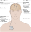
Technology of deep brain stimulation: current status and future directions
- PMID: 33244188
- PMCID: PMC7116699
- DOI: 10.1038/s41582-020-00426-z
Technology of deep brain stimulation: current status and future directions
Abstract
Deep brain stimulation (DBS) is a neurosurgical procedure that allows targeted circuit-based neuromodulation. DBS is a standard of care in Parkinson disease, essential tremor and dystonia, and is also under active investigation for other conditions linked to pathological circuitry, including major depressive disorder and Alzheimer disease. Modern DBS systems, borrowed from the cardiac field, consist of an intracranial electrode, an extension wire and a pulse generator, and have evolved slowly over the past two decades. Advances in engineering and imaging along with an improved understanding of brain disorders are poised to reshape how DBS is viewed and delivered to patients. Breakthroughs in electrode and battery designs, stimulation paradigms, closed-loop and on-demand stimulation, and sensing technologies are expected to enhance the efficacy and tolerability of DBS. In this Review, we provide a comprehensive overview of the technical development of DBS, from its origins to its future. Understanding the evolution of DBS technology helps put the currently available systems in perspective and allows us to predict the next major technological advances and hurdles in the field.
Conflict of interest statement
J. K. K. is a consultant for Medtronic and Boston Scientific. P. B. is a consultant for Medtronic. W. M. G. is the Director, Chief Scientific Officer and share owner of Deep Brain Innovations, LLC. He also receives royalty payments for licensed patents on temporal patterns of deep brain stimulation. M. I. H. has received travel expenses and honoraria from Boston Scientific for speaking at meetings. A. H. was supported by the German Research Council (DFG grant 410169619) and reports lecture fees from Medtronic and Boston Scientific unrelated to the present work. P. A. T. works as a consultant for Boston Scientific Neuromodulation. J. V. works as a consultant to Boston Scientific, Medtronic, and Newronika and has received honoraria for lectures from Boston Scientific and Medtronic as well as research grants from Boston Scientific and Medtronic. A. M. L. has served as a consultant for Boston Scientific, Medtronic, Aleva, and Abbott and is a co-founder of Functional Neuromodulation. All other authors declare no competing interests.
Figures


Similar articles
-
Implementation of New Technology in Patients with Chronic Deep Brain Stimulation: Switching from Non-Rechargeable Constant Voltage to Rechargeable Constant Current Stimulation.Stereotact Funct Neurosurg. 2019;97(5-6):362-368. doi: 10.1159/000505076. Epub 2020 Jan 16. Stereotact Funct Neurosurg. 2019. PMID: 31945765
-
Image-Guided, Asleep Deep Brain Stimulation.Prog Neurol Surg. 2018;33:94-106. doi: 10.1159/000480984. Epub 2018 Jan 12. Prog Neurol Surg. 2018. PMID: 29332076 Review.
-
Comparative connectivity correlates of dystonic and essential tremor deep brain stimulation.Brain. 2021 Jul 28;144(6):1774-1786. doi: 10.1093/brain/awab074. Brain. 2021. PMID: 33889943
-
Adaptive Brain Stimulation for Movement Disorders.Prog Neurol Surg. 2018;33:230-242. doi: 10.1159/000481107. Epub 2018 Jan 12. Prog Neurol Surg. 2018. PMID: 29332087 Review.
-
Shorter pulse generator longevity and more frequent stimulator adjustments with pallidal DBS for dystonia versus other movement disorders.Brain Stimul. 2014 May-Jun;7(3):345-9. doi: 10.1016/j.brs.2014.01.008. Epub 2014 Jan 18. Brain Stimul. 2014. PMID: 24548586 Free PMC article.
Cited by
-
Mesoscale neuronal granular trial variability in vivo illustrated by nonlinear recurrent network in silico.Nat Commun. 2024 Nov 15;15(1):9894. doi: 10.1038/s41467-024-54346-3. Nat Commun. 2024. PMID: 39548098 Free PMC article.
-
The effects of deep brain stimulation on sleep: a systematic review and meta-analysis.Sleep Adv. 2024 Oct 22;5(1):zpae079. doi: 10.1093/sleepadvances/zpae079. eCollection 2024. Sleep Adv. 2024. PMID: 39525613 Free PMC article. Review.
-
The expanding horizon of neurotechnology: Is multimodal neuromodulation the future?PLoS Biol. 2024 Oct 28;22(10):e3002885. doi: 10.1371/journal.pbio.3002885. eCollection 2024 Oct. PLoS Biol. 2024. PMID: 39466832 Free PMC article.
-
Neural interfaces: Bridging the brain to the world beyond healthcare.Exploration (Beijing). 2024 Mar 14;4(5):20230146. doi: 10.1002/EXP.20230146. eCollection 2024 Oct. Exploration (Beijing). 2024. PMID: 39439491 Free PMC article.
-
Wireless closed-loop deep brain stimulation using microelectrode array probes.J Zhejiang Univ Sci B. 2024 Feb 12;25(10):803-823. doi: 10.1631/jzus.B2300400. J Zhejiang Univ Sci B. 2024. PMID: 39420519 Free PMC article. Review.
References
-
- Fasano A, Aquino CC, Krauss JK, Honey CR, Bloem BR. Axial disability and deep brain stimulation in patients with Parkinson disease. Nat Rev Neurol. 2015;11:98–110. - PubMed
-
- Limousin P, Foltynie T. Long-term outcomes of deep brain stimulation in Parkinson disease. Nat Rev Neurol. 2019;15:234–242. - PubMed
-
- Fontaine D, Vandersteen C, Magis D, Lanteri-Minet M. Neuromodulation in cluster headache. Adv Tech Stand Neurosurg. 2015;42:3–21. - PubMed
Publication types
MeSH terms
Grants and funding
LinkOut - more resources
Full Text Sources
Other Literature Sources
Miscellaneous


