iBet uBet web content aggregator. Adding the entire web to your favor.


Link to original content: http://pubmed.ncbi.nlm.nih.gov/34393748/
Spontaneous Gait Transitions of Sprawling Quadruped Locomotion by Sensory-Driven Body-Limb Coordination Mechanisms - PubMed Skip to main page content
U.S. flag

An official website of the United States government

Dot gov

The .gov means it’s official.
Federal government websites often end in .gov or .mil. Before sharing sensitive information, make sure you’re on a federal government site.

Https

The site is secure.
The https:// ensures that you are connecting to the official website and that any information you provide is encrypted and transmitted securely.

Access keys NCBI Homepage MyNCBI Homepage Main Content Main Navigation
. 2021 Jul 30:15:645731.
doi: 10.3389/fnbot.2021.645731. eCollection 2021.

Spontaneous Gait Transitions of Sprawling Quadruped Locomotion by Sensory-Driven Body-Limb Coordination Mechanisms

Affiliations

Spontaneous Gait Transitions of Sprawling Quadruped Locomotion by Sensory-Driven Body-Limb Coordination Mechanisms

Shura Suzuki et al. Front Neurorobot. .

Abstract

Deciphering how quadrupeds coordinate their legs and other body parts, such as the trunk, head, and tail (i.e., body-limb coordination), can provide informative insights to improve legged robot mobility. In this study, we focused on sprawling locomotion of the salamander and aimed to understand the body-limb coordination mechanisms through mathematical modeling and simulations. The salamander is an amphibian that moves on the ground by coordinating the four legs with lateral body bending. It uses standing and traveling waves of lateral bending that depend on the velocity and stepping gait. However, the body-limb coordination mechanisms responsible for this flexible gait transition remain elusive. This paper presents a central-pattern-generator-based model to reproduce spontaneous gait transitions, including changes in bending patterns. The proposed model implements four feedback rules (feedback from limb-to-limb, limb-to-body, body-to-limb, and body-to-body) without assuming any inter-oscillator coupling. The interplay of the feedback rules establishes a self-organized body-limb coordination that enables the reproduction of the speed-dependent gait transitions of salamanders, as well as various gait patterns observed in sprawling quadruped animals. This suggests that sensory feedback plays an essential role in flexible body-limb coordination during sprawling quadruped locomotion.

Keywords: body-limb coordination; decentralized control; gait transition; salamander locomotion; sensory feedback control.


Conflict of interest statement

The authors declare that the research was conducted in the absence of any commercial or financial relationships that could be construed as a potential conflict of interest.

Figures

Figure 1
Figure 1
Body model. The trunk has n − 1 actuated degrees of freedom (DoFs), and θjb denotes the angle of the j-th DoF from the head. The fore- and hind-legs are attached on both sides of the k-th and l-th segments, respectively (in the figure, n = 11, k = 3, and l = 7). Each leg has two DoFs controlled by phase oscillators. The subscript i denotes the leg identifier: (1, left fore; 2, right fore; 3, left hind; and 4, right hind), and θiy and θir are the angles of the leg joints in the yaw and roll directions, respectively. The circle around the right foreleg shows the leg trajectory based on the oscillator phase ϕi. Variables mJ, mL, and mF are the masses of each joint, link, and foot, respectively.
Figure 2
Figure 2
Configuration of the feedback network. The circles and triangles represent the controllers and sensors, respectively. Each leg controller has one phase oscillator. The arrows show the four types of sensory feedback; blue indicate the force feedback from limb to limb and limb to body, orange indicates the torque feedback from body to limb, and gray indicates the angle feedback from body to body.
Figure 3
Figure 3
Schematic of body-limb sensory feedback. (A) Schematic of the salamander robot model from the top view. The squared region around the forelegs indicates the body part illustrated by (B,C) to explain the feedback effect. (B) Body-to-limb sensory feedback mechanism: (i) the k-th trunk actuator bends the body to the right (τkb>0) and (ii) the k-th trunk actuator bends the body to the left (τkb<0). When the k-th trunk actuator bends the body to the right, the left foreleg oscillator phase is modulated toward π/2 (to swing), and the right foreleg oscillator phase is modulated toward 3π/2 (to stance), and vice versa. (C) Limb-to-body sensory feedback mechanism: (i) the right foreleg is on the ground (N2 > 0) and (ii) the left foreleg is on the ground (N1 > 0).
Figure 4
Figure 4
Spontaneous gait transition from L-S walk with standing waves to walking trot with traveling wave and vice versa. The upper graph represents the lateral flexion of the trunk joint, wherein the colored region denotes the period when the trunk joint bends to the right (θjb>0). The lower graph represents the gait diagram, wherein the colored region denotes the period when the foot is in contact with the ground (Ni > 0). We set the parameter ω from 1.8 π to 3.8 π [rad/s] at period 16 [s], and from 3.8 π to 1.8 π [rad/s] at period 22 [s]. We confirmed that the gait transition was observed for any initial oscillator phase (for all 10 trials).
Figure 5
Figure 5
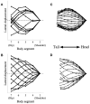
Simulated robot (left) and salamander D. teneborosus (right) during locomotion. The stick figures were made by connecting the positions of the body parts over the midline. All stick figures throughout one gait cycle were superimposed by lining them up on the anteriormost part of the body trunk. (A) Simulated robot for ω = 1.8π, (B) simulated robot for ω = 3.8π, (C) D. teneborosus while walking, (D) D. teneborosus while trotting. (C,D) Adapted from the Ashley-Ross's study (Ashley-Ross, 1994), with permission.
Figure 6
Figure 6
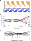
Lateral-sequence walking with intermediate waves of lateral bending. The proposed model without any modified parameter except for the control parameter ω reproduced the gait pattern, as listed in Table 1. (A) The upper graph represents the lateral flexion of the trunk joint, wherein the colored region denotes the period when the trunk joint bends to the right (θjb>0). The lower graph represents the gait diagram, wherein the colored region denotes the period when the foot is in contact with the ground (Ni > 0). (B) Waveform of lateral bending of the simulated robot. The superimposed figure was made from 12 stick figures. The stick figures were produced by connecting the lateral displacement of body segments from the center of mass (CoM). The moment of each stick figure is time-shifted every 1/12 gait cycle, and the line colors show the order of the stick figures (red: 1st and 7th; orange: 2nd and 8th; green: 3rd and 9th; cyan: 4th and 10th; blue: 5th and 11th; and violet: 6th and 12th). Note that the 1st and 7th stick figures are time-shifted by a half period of the gait cycle, thereby being mirror images of one another (the mirror images are in the same line color). (C) Waveform of lateral bending when Dipsosaurus dorsalis exhibits intermediate waves, adapted from Ritter (1992), with permission. The figure was made by a similar method to that applied for (B). The numbered lines indicate points of minimal lateral displacement in each stick figure.
Figure 7
Figure 7
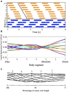
Lateral-sequence walking gait with traveling waves of lateral bending. The proposed model (with modified feedback gain parameters) reproduced the gait pattern, as listed in Table 1. (A) The upper graph represents the lateral flexion of the trunk joint, wherein the colored region denotes the period when the trunk joint bends to the right (θjb>0). The lower graph represents the gait diagram, wherein the colored region denotes the period when the foot is in contact with the ground (Ni > 0). (B) Waveform of lateral bending of the simulated robot. The superimposed figure was made from 12 stick figures. The stick figures were produced by connecting the lateral displacement of body segments from the center of mass (CoM). The moment of each stick figure is time-shifted every 1/12 gait cycle, and the line colors show the order of the stick figure (red: 1st and 7th; orange: 2nd and 8th; green: 3rd and 9th; cyan: 4th and 10th; blue: 5th and 11th; violet: 6th and 12th). Note that the 1st and 7th stick figures are time-shifted by a half period of the gait cycle, thereby being mirror images of one another (the mirror images are in the same line color). (C) Waveform of lateral bending when Gerrhonotus kingii exhibits traveling waves, adapted from Ritter (1992), with permission. The figure was made by a similar method to that applied for (B). The numbered lines indicate points of minimal lateral displacement in each stick figure.
Figure 8
Figure 8
Color maps showing the two indices; diagonality and the waveform index, when the intrinsic angular velocity ω is between 1.5π and 4.0π, and the feedback gain from limb-to-limb σLL is between 0.00 and 7.50. (A) diagonality (σLB = 7.0, σBB = 7.7), (B) waveform index (σLB = 7.0, σBB = 7.7), (C) diagonality (σLB = 4.5, σBB = 5.0), (D) waveform index (σLB = 4.5, σBB = 5.0). In (A,C), the brighter region indicates a higher diagonality. In (B,D), the brighter region shows that a traveling wave emerges. The fluctuation in the upper left part of (C,D) indicates that an unstable locomotion emerged, and the gait was not evaluated correctly. The squared regions indicate the parameter sets used in the other experiments (red: Figure 4 for ω = 1.8π described in section 3.1; blue: Figure 4 for ω = 3.8π described in section 3.1; yellow: Figure 6 described in section 3.2; and purple: Figure 7 described in section 3.2).
Figure 9
Figure 9
Color maps showing the two indices; diagonality and the waveform index, when the body size and mass are between 50 and 150%, (A) diagonality, (B) waveform index. In (A), the brighter region indicates a higher diagonality. In (B), the brighter region shows that the waveform is relatively similar to the traveling waves. The control parameter set was used in Figure 6 is described in section 3.2; for the L-S walk with intermediate waves.

Similar articles

Cited by

References

    1. Ashley-Ross M. (1994). Hindlimb kinematics during terrestrial locomotion in a salamander (Dicamptodon tenebrosus). J. Exp. Biol. 193, 255–283. 10.1242/jeb.193.1.255 - DOI - PubMed
    1. Bicanski A., Ryczko D., Cabelguen J.-M., Ijspeert A. J. (2013a). From lamprey to salamander: an exploratory modeling study on the architecture of the spinal locomotor networks in the salamander. Biol. Cybern. 107, 565–587. 10.1007/s00422-012-0538-y - DOI - PubMed
    1. Bicanski A., Ryczko D., Knuesel J., Harischandra N., Charrier V., Ekeberg Ö., et al. . (2013b). Decoding the mechanisms of gait generation in salamanders by combining neurobiology, modeling and robotics. Biol. Cybern. 107, 545–564. 10.1007/s00422-012-0543-1 - DOI - PubMed
    1. Cabelguen J.-M., Bourcier-Lucas C., Dubuc R. (2003). Bimodal locomotion elicited by electrical stimulation of the midbrain in the salamander notophthalmus viridescens. J. Neurosci. 23, 2434–2439. 10.1523/JNEUROSCI.23-06-02434.2003 - DOI - PMC - PubMed
    1. Cartmill M., Lemelin P., Schmitt D. (2002). Support polygons and symmetrical gaits in mammals. Zool. J. Linnean Soc. 136, 401–420. 10.1046/j.1096-3642.2002.00038.x - DOI

LinkOut - more resources